Dual Wall Pipe Installation Guide
(Complying with ASTM F2648 & EN 13476 Standards)
I. Construction Sequence
- Survey & Marking → 2. Mechanical Trenching → 3. Subgrade Compaction → 4. Gravel Base Course → 5. Sand Bedding → 6. Pipe Installation → 7. Manhole Construction → 8. Backfilling → 9. Hydrostatic Test → 10. Final Compaction
 II. DWCP Installation Protocol
1. Pre-Construction Preparation
- Review design drawings to confirm pipeline layout, slopes, and connection requirements
- Verify existing control points (benchmarks & traverse points) along the alignment
- Conduct topographic survey, plot as-built sketches, and establish temporary control points
2. Trench Excavation
| Parameter | Requirement |
|---|
| Trench Width | Pipe OD + 0.4–1.0m (min. 600mm working space) |
| Slope Ratio | As per design (typically 1:0.33–1:1 for cohesive soils) |
| Undisturbed Soil | Preserve 200–300mm above design grade; trim manually before pipe laying |
| Over-Excavation | Backfill with 10–15mm graded gravel or coarse sand (≥95% compaction) |
| Groundwater Control | Install sump pumps + 100mm gravel drainage layer where required |
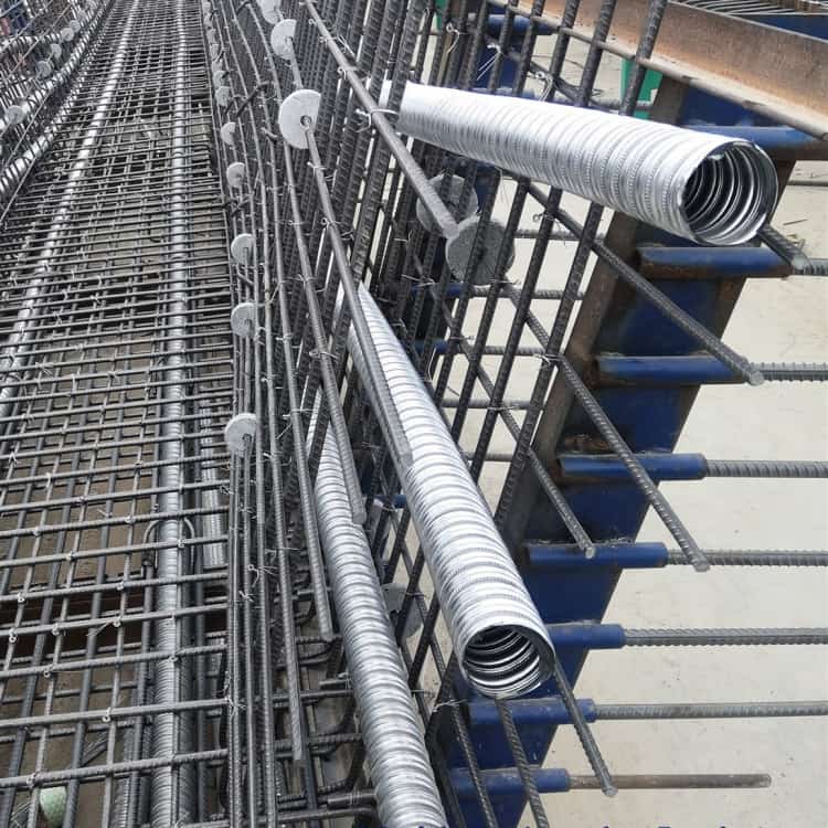
3. Pipe Foundation
| Soil Condition | Foundation Specification |
|---|
| Stable Soil | 100mm sand bedding (CBR ≥5%) |
| Waterlogged Soft Soil | 150mm crushed stone (5–40mm) + 50mm sand layer (Total ≥200mm) |
| Organic Soil | 300mm graded Gobi gravel replacement |
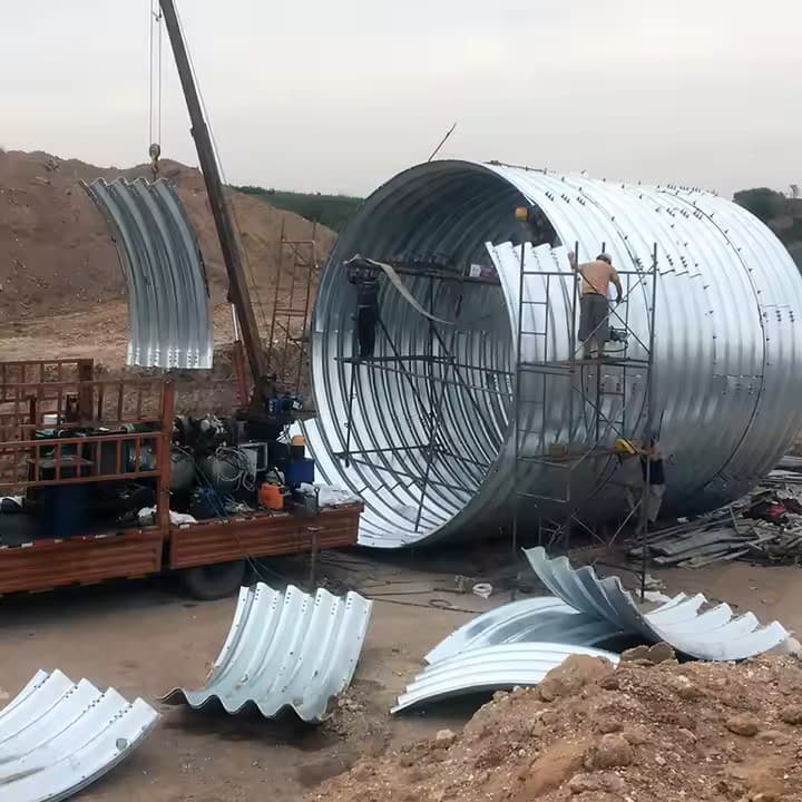
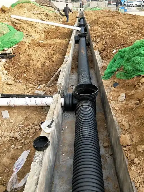
4. Pipe Installation
- Jointing Method: Snap-tight couplings with EPDM gaskets (per ASTM D3212)
- Alignment Tolerance: ±10mm vertical/horizontal deviation per 3m length
- Deflection Limit: ≤5% of nominal diameter (post-installation)
5. Quality Control Checks
| Stage | Inspection Items |
|---|
| Pre-Installation | Pipe certification (ISO 9001), ovality (<3%), rubber ring hardness (50–60 IRHD) |
| During Installation | Bedding compaction, joint seating depth, pipe invert elevation (±15mm) |
| Post-Installation | Hydrostatic test (1.5× working pressure for 30min), deflection measurement |
 Dual Wall Pipe Installation Guide
III. Critical Technical Requirements
1. Backfilling
- Initial Layer: Select backfill to pipe springline (≤300mm lifts, 90% compaction)
- Final Layer: Native soil in 500mm lifts (≥95% compaction for road sections)
2. Manhole Integration
- Use flexible boot adapters (per ASTM C923) at pipe-manhole connections
- Apply bentonite waterstop at penetration points
3. Testing Protocols
- Mandrel Test: Pass 95% pipe diameter mandrel through installed pipeline
- Leakage Test: Max 1.25 l/km/day for diameters ≤1000mm (per EN 1610)
 Ⅳ. Pipe Installation
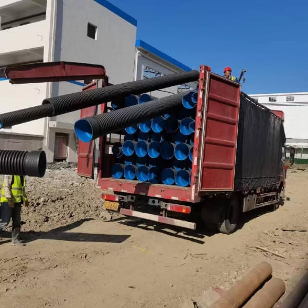
1. Handling & Placement
| Method | Specification |
|---|
| Manual Installation | Lift pipe ends to trench workers (max. 3m depth or ≤DN400 pipes) |
| Mechanical Lowering | Use non-metallic slings for >3m depth/DN400+ pipes (metallic tools prohibited) |
| Alignment Tolerance | ±10mm vertical/horizontal deviation per 3m length |
2. Jointing Techniques
- Socket-Spigot Joints: Install with spigot facing downstream (per ISO 8639)
- Spiral Corrugated Joints:
- Methods: Electrofusion, extrusion welding, or heat-shrink sleeves
- Tolerance: Max. 2mm radial misalignment
3. Quality Control
- Cutting: Use fine-tooth saws for square cuts (burr-free)
- Gasket Inspection: Verify O-ring position with feeler gauge (0.5-1.0mm gap)
- Elevation Check: Measure crown elevation every 10m (converted to invert)
Ⅴ. Manhole Connection
1. Connection Methods
| Type | Technical Requirements |
|---|
| Flexible Joint | Pre-installed EPDM boot adapter (min. 100mm overlap) |
| Rigid Connection | M10 cement mortar with 5% calcium sulfoaluminate expansion agent |
| Precast Collar | C15 concrete collar (ID=pipe OD+20mm, thickness≥50mm) + rubber gasket |
Ⅵ. Backfilling Protocol
1. Compaction Requirements
| Zone | Compaction (%) | Material |
|---|
| Pipe Foundation | 85-90 | Washed sand (0.5-2mm) |
| Pipe Haunches (2α zone) | 95 | Graded gravel (5-40mm) |
| Pipe Springline to 0.5m | 90/85* | Select backfill (≤10% fines) |
| Above 0.5m | ≥80 | Native soil |
*Note: 90% for sides, 85% for top
2. Special Conditions
- High Water Table: Install geotextile (200g/m²) + underdrains
- Uneven Settlement: Use flowable fill (CLSM) for transition zones
Ⅶ. Pressure Testing
1. Hydrostatic Test
- Procedure: Fill to 2m head pressure for 24hrs (per GB 50268)
- Allowable Leakage: ≤1.25 L/km/day for DN≤1000mm
2. Alternative Methods
- Air Test: 25kPa for 5min (max. 0.5kPa pressure drop)
Ⅷ. Deformation Inspection
1. Post-Installation Check
- Timeframe: Measure within 12-24hrs after final backfill
- Tolerance: Max. 3.3% diameter deflection (2/3 of allowable)
2. Corrective Actions
- Expose 85% pipe height (manual excavation within 0.5m)
- Replace damaged sections
- Recompact with ASTM D698 compliant material
 II. DWCP Installation Protocol
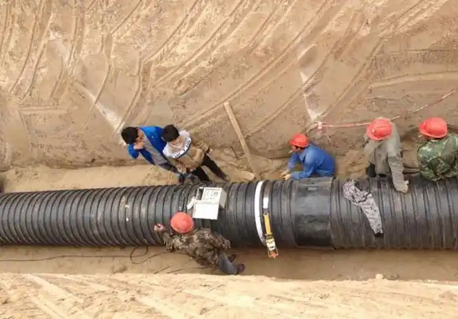
 Ⅳ. Pipe Installation