Prestressed Corrugated Metal Ducts Installation Guide (PCMD)
(For Post-Tensioning Applications per ASTM A929/A929M & EN 523)
1. Functions & Advantages
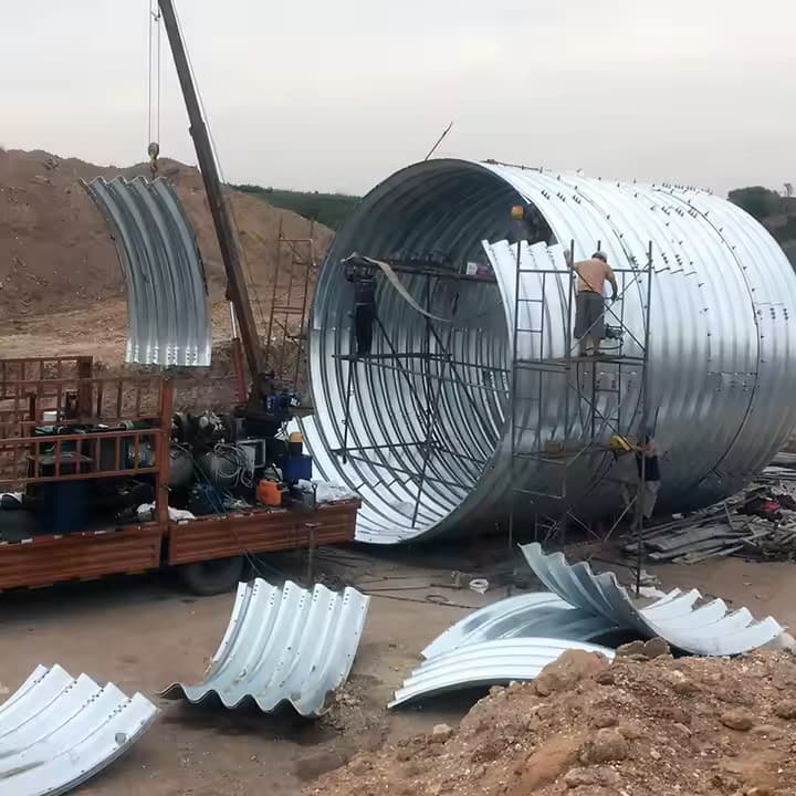
Prestressed corrugated metal ducts are fabricated from galvanized/non-galvanized steel strips through spiral folding and lock-seam forming. Key benefits include:
- Structural Performance: Provides secure conduits for tendons, preventing corrosion from concrete bleed water (pH≥12.5) and atmospheric moisture (RH≤75%).
- Construction Efficiency: Lightweight (0.8-1.2kg/m for Ø50mm) with bend radii ≥30×D without kinking.
- Bond Enhancement: Helical grooves (pitch: 6-12mm) improve 28-day grout bond strength by 40% vs. smooth ducts.
2. Pre-Installation Preparations
2.1 Material Inspection
- Visual Checks: Reject ducts with:
- Dents >3% of diameter
- Zinc coating defects (<100g/m² per ISO 1461)
- Seam gaps >0.5mm
- Dimensional Tolerance:
Parameter Allowance Diameter ±1.5mm Wall thickness ±0.1mm

2.2 Site Preparation
- Clearance: Maintain 500mm working space around duct routes.
- Tool Checklist:
- Torque wrench (10-50Nm range)
- Seam crimper (for field joints)
- Leak tester (0.3MPa air pressure)
2.3 Layout & Positioning
- Tolerance Limits:
- Vertical: ±10mm (per EN 1992-1-1)
- Horizontal: ±20mm
- Marking: Use laser levels for curves (min. radius=4m).
3. Installation Procedures
3.1 Jointing Methods
A. Sleeve Connections
- Select sleeves 10mm larger than duct Ø (e.g., Ø60mm sleeve for Ø50mm duct).
- Insert ducts 150mm minimum into sleeve.
- Seal with:
- Butyl tape (3mm thick, 50% overlap)
- Stainless steel hose clamps (2 clamps/joint, torque to 8Nm).
B. Spigot-and-Socket Joints
- Chamfer spigot end at 15°.
- Apply polysulfide sealant (ASTM C920 Type M) to socket.
- Engage with ¼ turn until alignment marks match.
3.2 Fixing to Reinforcement
- Spacing:
Segment Type Interval Straight 800mm max. Curved 400mm max. - Binding: Use 1.2mm annealed wire (2 turns per strap).
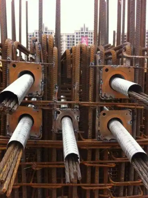
3.3 Anchorage Connection
- Insert duct 50mm into trumpet.
- Weld/seal per:
- Option 1: 3 tack welds (max. 150°C to avoid zinc vaporization)
- Option 2: Epoxy putty (24h cure @20°C)
3.4 Leak Prevention
- Critical Areas:
- Penetrations: Wrap with hydrophilic waterstop
- Couplers: Pressure-test at 0.2MPa for 5min
 4. Key Operational Controls
 4. Key Operational Controls
4.1 Concrete Placement
- Pouring: Maintain 300mm free-fall distance from ducts.
- Vibration:
- Minimum offset: 300mm from duct surface
- Frequency: ≤10,000 rpm to avoid seam resonance
4.2 Pre-Stressing Checks
- Mandrel Test: Pass Ø90% tendon diameter mandrel through entire run.
- Airflow Test: ≤3% pressure drop in 10min @0.15MPa.
4.3 Grouting Protocol
- Flushing: Pump pH 7-8 water at 0.5m/s velocity.
- Mixing:
- W/C ratio: 0.40±0.02
- Marsh cone flow: 25-35 seconds
- Injection:
- Pressure: 0.5-1.0MPa
- Venting: Continue until effluent density matches inlet (±2%).
5. Troubleshooting Guide
| Issue | Root Cause | Solution |
|---|---|---|
| Seam leakage | Insufficient crimp force | Re-crimp at 15% higher pressure |
| Grout voids | Rapid setting (<30min) | Use retarding admixture (0.1% by weight) |
| Tendon seizure | Duct ovalization (>5%) | Install internal stiffener sleeve |
6. Maintenance
- Exposed Sections: Apply zinc-rich paint (DFT≥80μm) annually.
- Structural Monitoring: Use ultrasonic tomography if cracks >0.3mm appear.
This guide complies with PTI M50.3-20 and FIB Bulletin 33 standards. For seismic zone adaptations (Z≥3), consult Section 8.4 of EN 1998-1.
Would you like to include the manufacturer’s inspection checklist for grout acceptance testing?